Drawing points with Babylon.js…
…What an exciting topic, isn’t it?
Just use a Point Cloud System or a Solid Particle System and you’re done, end of story, next topic!
Of course, there’s more to it than that (otherwise this post wouldn’t exist), when you add specific constraints that make the task a little more challenging.
So stay tuned, you might even learn some new WebGL stuff in the process!

The problem
The starting point (no pun intended!) of the journey was to port native code that renders the vertices of a mesh as points, on top of the mesh, like this:

The native code uses a geometry shader, which trivializes the task. It simply passes the three vertices of the triangle (in world space coordinates) to the fragment shader. All the fragment shader has to do is calculate the distance between the currently shaded pixel and the three vertices, and if the distance is small enough (within the radius of the point you want to draw), use a solid color instead of the true color of the material.
Problem: WebGL / WebGL2 does not support geometry shaders!
We therefore had to find a workaround to ensure that this could be done within the constraints of WebGL.
Additional Constraints
So why not render the vertices with a Particle Cloud System or a Solid Particle System, as mentioned in the introduction? Seems like it might work?

Firstly, as this would be an additional rendering on an existing mesh, we’d need to use the z-offset material property to ensure that the points appear on the mesh and don’t cause z-fighthing with it. As anyone who has used the z-offset property knows, working with it is usually a pain in the *ss, as it’s a kind of arbitrary value you have to use, which will depend on your scene and meshes: one value may work in some cases and not in others. Another problem with this property is that it’s not currently supported by Babylon Native, and the solution we find will have to work with this engine too!
Secondly, and more importantly, the solution must work even if a mesh uses bone and/or morph animations (and, ideally, with any custom vertex transformations that might be applied inside a vertex shader)! The Particle Cloud System and the Solid Particle System will not work in this case, because vertices transformed by the influence of bones and morphs are not available to these classes.
The (A) solution
Given the need to support bone/morph constraints, we decided that the solution should be implemented by a material plugin. In this way, the new code would be injected into the existing shader code and would naturally support any vertex deformation that takes place in the vertex shader.
As for the shader code itself, we needed to find a way to render the three points of the three vertices of a triangle, but without a geometry shader…
It’s possible to do this for a single vertex quite easily:
- calculate the vertex’s world position in the vertex shader
- pass the value to the fragment shader using the flat qualifier
The flat qualifier tells the GPU rasterizer NOT to interpolate the value when rasterizing the triangle: the same value will be passed to the fragment shader for all pixels in the triangle. Simply calculate the distance of the current pixel (in world space) with the value passed to the fragment shader, and use a fixed color if this distance is smaller than the radius of the point you wish to display.
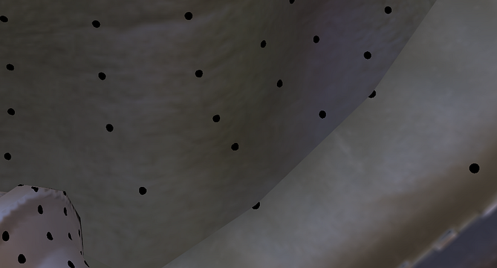
Here’s what you get if you do this (link to PG):

It’s not obvious, but it works! You don’t get a nice rounded point because each triangle draws only the part of the point that lies inside the triangle. So, for each triangle and for one of its vertices (which one is explained below), only a part (arc) of a disk is drawn instead of a complete disk. Adjacent triangles (which share the same vertex) do the same, but the rasterizer may not use the same vertex for each triangle when you transmit the vertex’s world position with the flat qualifier.
This is where you may learn a new WebGL concept, namely “provoking vertex”. When you pass a variable from the vertex to the fragment shader using the flat qualifier, the rasterizer is free to choose the value from any of the three vertices that define a triangle: there’s no reason to choose the value from vertex A instead of vertex B or C, for example. By convention and by default, WebGL uses the last vertex as the provoking vertex. So, in the example above, the value would come from vertex shader execution for vertex C and would be used for the execution of all fragments of this triangle.
Drawing a full disk
So, armed with this knowledge, you can understand why we don’t get a full disk in the example above: it’s because the provoking vertex may not be the same for all the triangles that share a given vertex. For example, if a vertex C is shared by three triangles, the first triangle being defined in the order (A,B,C), the second in the order (C,B,D) and the third in the order (D,A,C), the vertex C is the provoking vertex only for the first and third triangles, so we obtain two-thirds of a disk rendered at C instead of a complete disk.
We could achieve what we want (drawing a complete disc for each vertex) if we could draw a triangle three times and choose a different provoking vertex each time. This way, each triangle would render the portion of the disk corresponding to each of its three vertices, and when all the triangles were rendered, all the portions of the disk would be connected and we’d get full points. This algorithm fails on the edges of the mesh because some of the triangles that share a vertex located on the edge are not visible, but that’s fine with us:
Drawing the same triangle three times is very easy: simply “triplicate” a triangle definition in the index buffer! And, to handle the fact that we want to use a different provoking vertex each time, simply rotate the definition. So, if a triangle is defined by the indices (I1, I2, I3), add (I2,I3,I1) and (I3,I1,I2) to the index buffer.
Et voilà, nice rounded dots (link to PG):
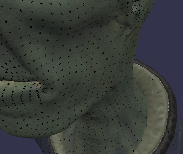
Hem, not quite, it’s the same picture than above…
Fixing the rendering
What happens is that the third rendering of each triangle overwrites the first and second, so that in the end, only one vertex per triangle is rendered correctly.
We need the second and third renders not to overwrite the previous render. Again, this is easy enough to achieve: if the distance between the current pixel (in world space) and the vertex position passed to the fragment shader with the flat qualifier is less than the point radius, use a fixed color, otherwise use the discard instruction to leave the current pixel color unchanged. Note that this works because we use LEQUAL (“Less or equal”) for the depth function. This means that when rendering the second and third versions of each triangle, the colors generated by the fragment shader will effectively overwrite the current color (assuming we don’t pass in the discard branch) thanks to the “or equal” part of the depth function: the three triangles are exactly the same, so the depth calculated by the GPU is exactly the same for all pixels over the three renderings.
Implementing this method is a little more difficult than we would like, as we have to differentiate between the (vertices of the) first triangle and the (vertices of the) second/third triangles:
- for the first triangle, we want to render it entirely, with the material color calculated for all the triangle’s pixels except the vertex corresponding to the provoking vertex for which we want to draw the portion of the point
- for the second and third triangles, we want to draw only the points and leave the other pixels unmodified
The only way we found was to pass an “initialPass” information (rendering of the first or second/third triangle) to the vertex shader by means of an attribute (with the value 1 for the vertices of the first triangle and 0 for the vertices of the second/third triangle). But when we “triplicated” the triangle, we simply used the same vertex indices, but in a different order! The new triangles use the same vertices as the first triangle, so it’s not possible to pass a different value for “initialPass” for the first triangle than for the second/third triangle. For this to work, we must first un-index the mesh, which will create new vertices and ensure that each triangle has its own set of vertices, not shared with any other triangle. In Babylon.js, there’s a handy convertToUnIndexedMesh function on the Mesh class that performs this operation.
Once the mesh is un-indexed, we can easily create the “initialPass” attribute, and here’s what you get (link to PG):
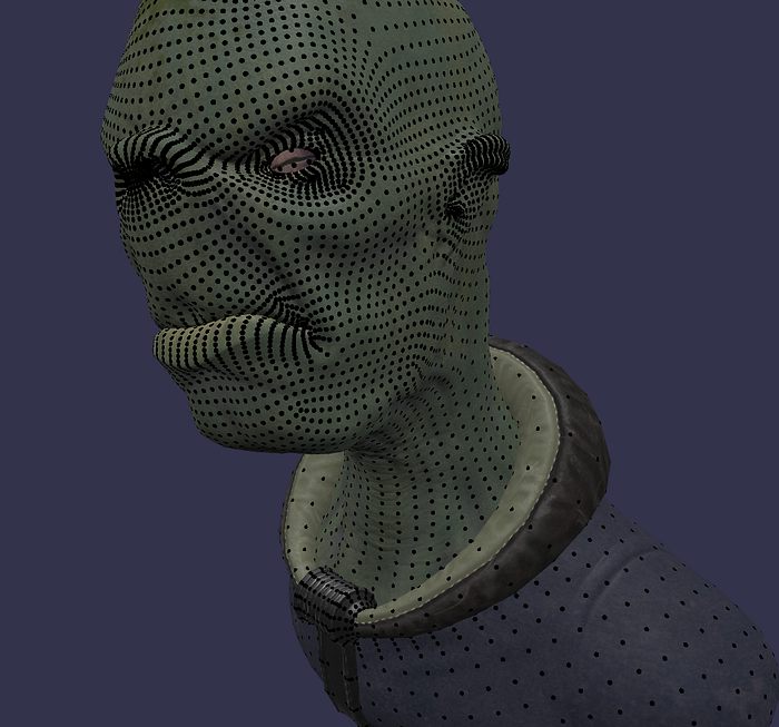
Hurray, this time it works!
A final optimization
In the PG above, we un-index the mesh after “triplicating” each triangle in the indexing buffer, resulting in vertex buffers three times larger than before the un-indexing process.
We can do better by only doubling the size of the vertex buffer if we create a single duplicate before the un-indexing process and create the third version of each triangle afterwards, reusing the same vertices used by the second version of the triangles. Sharing vertices between the second and third triangles poses no problem, as the “initialPass” attribute has the same value in both cases. Note that for this to work, we need to “re-index” the mesh, as the third version of the triangles is now based on new entries in the index buffer! In Babylon.js, mesh.isUnIndexed = false will do the trick.
Here’s the PG for the final version:
Note that this code has been integrated into the excellent mesh debugging plugin created by Alexandra. So you can do the same thing (and much more, see MeshDebugPluginMaterial) in a much simpler way:
Conclusion
So what seemed like a simple task ended up being a lot of work!
What’s more, it’s far from perfect:
- Vertex buffers are doubled in size. In fact, they are more than doubled due to the un-indexing process!
- We render three times as many triangles as when we render the mesh without points. In fact, this isn’t so bad, because for the second and third triangles, we quickly leave the fragment shader when we’re not in the point radius, which normally happens most of the time (unless you have very small triangles and/or want to display very large points).
- We need to create a new attribute to pass the “initialPass” data to the vertex shader. Since attributes are a scarce resource, it’s not always possible to create a new one if you’ve already reached the limit.
Nevertheless, this solution is acceptable to us as the code is used in a debugging component and is not intended to be used directly in production code.
However, if you think you can find a better solution given the constraints detailed in this post, don’t hesitate to join the forum and share your findings with us!
Popov — Babylon.js Team